# Config Routeur/SwitchL2-L3 AP
### Rappel schéma Infra
[](https://sioaubusson.fr/uploads/images/gallery/2026-03/I7Wimage.png)
### Rappel tableau VLANS
[](https://sioaubusson.fr/uploads/images/gallery/2026-03/F9vimage.png)
### Documentation Routeur
COM4
Utilisateur : cisco
Mdp : caribou23000,
Tout d'abord nous allons configurer le port de notre routeur qui sera relié au réseau du lycée. Le port gi4 du routeur sera configuré en DHCP.
int gi4
ip add dhcp
Cette commande configure le port gi4 en DHCP ce qui nous permet par la suite d'obtenir une adresse IP du réseau du lycée.
Ensuite nous allons configurer le port qui sera donc relié au LAN c'est à dire notre réseau local.
int gi5
ip add 192.168.80.2 255.255.255.252
ip route 0.0.0.0 0.0.0.0 10.123.33.245
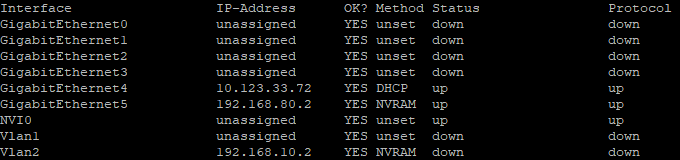
Pour vérifier la configuration nous pouvons faire la commande :
#sh ip int brief
[](https://sioaubusson.fr/uploads/images/gallery/2026-03/DWiimage.png)
L'adresse réseau 192.168.80.0/29 représente le VLAN 9 ou Sortie, de notre réseau LAN GSB.
Une fois nos deux port fini de configurer nous pouvons attaquer la NAT, pour cela nous allons définir un port en outside (dehors du réseau) et inside (interne au réseau).
Nous allons donc définir le port gi5 en inside et le port gi4 en outside. Ensuite nous allons faire une ACL pour le VLAN 9 à l'aide de l'adresse réseau 192.168.80.0 et le masque générique donc pour 255.255.255.252 cela devient 0.0.0.3.
int gi5
ip nat inside
int gi4
ip nat outside
access-list 1 permit 192.168.80.0 0.0.0.3 -> VLAN
ip nat inside source list 1 interface gi4 overload
Si besoin nous pouvons ajouter autant de vlan que nous voulons, dans notre cas nous y ajouterons les VLANS nécessaire pour le réseau GSB pour cela :
access-list 2 permit 192.168.10.0 0.0.0.255 -> VLAN Administrateur
access-list 2 permit 192.168.20.0 0.0.0.255 -> VLAN Accueil/Visiteur
access-list 2 permit 192.168.30.0 0.0.0.255 -> VLAN Direction/DSI
access-list 2 permit 192.168.40.0 0.0.0.255 -> VLAN RH
access-list 2 permit 192.168.50.0 0.0.0.255 -> VLAN Communication
access-list 2 permit 192.168.60.0 0.0.0.255 -> VLAN Commercial
access-list 2 permit 192.168.70.0 0.0.0.255 -> VLAN Démonstration/ Salle de Réunion
access-list 2 permit 192.168.90.0 0.0.0.15 -> VLAN Front
access-list 2 permit 192.168.100.0 0.0.0.15 -> VLAN BACK
access-list 2 permit 192.168.110.0 0.0.0.7 -> VLAN Sécurité
access-list 2 permit 192.168.120.0 0.0.0.3 -> VLAN Proxmox
access-list 2 permit 192.168.130.0 0.0.0.255 -> VLAN Client
ip nat inside source list interface gi4 overload
Maintenant toutes nos règles NAT sont fini d'être mise en place nous pouvons ainsi commencer la configuration de notre Switch L3.
### Documentation Switch L3
COM5
Utilisateur : cisco
Mdp : caribou23000,
Dans notre Switch L3 Catalyst-1300 nous y indiquerons tous nos VLANS de notre réseau GSB pour cela nous allons utiliser notre tableau de VLAN, pas besoin de configurer les VLANS qui seront présent dans le PVE car L'OPNsense va de son côté attribuer les adresses aux VLANS.
vlan 2,3,4,5,6,7,8,9,10,11,12,13,14,99
(conf) int vlan 2
ip add 192.168.10.1 255.255.255.0
int vlan 3
ip add 192.168.20.1 255.255.255.0
int vlan 4
ip add 192.168.30.1 255.255.255.0
int vlan 5
ip add 192.168.40.1 255.255.255.0
int vlan 6
ip add 192.168.50.1 255.255.255.0
int vlan 7
ip add 192.168.60.1 255.255.255.0
int vlan 8
ip add 192.168.70.1 255.255.255.0
int vlan 9
ip add 192.168.80.1 255.255.255.252
int vlan 99 -> Correspond au VLAN Vide
ip add 192.168.99.1 255.255.255.0
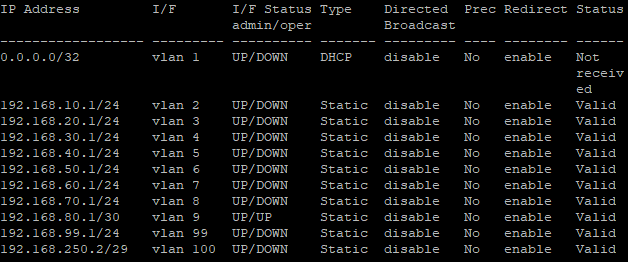
Ensuite pour vérifier que tous nos VLANS ont bien été créé nous pouvons faire la commande :
\#sh ip int
[](https://sioaubusson.fr/uploads/images/gallery/2026-03/krtimage.png)
Maintenant que nos VLANS sont tous bien été déclarés, nous pouvons dès à présent configurer les ports du Switch L3.
Nous allons commencer par configurer le port reliant notre Switch L3 à notre Routeur et ensuite le port reliant le Switch L3 à notre Switch L2.
int gi1 -> Port relié au Routeur
switchport mode access
switchport access vlan 9 -> VLAN Sortie
int gi2 -> Port relié au Proxmox
switchport mode trunk
switchport trunk allowed vlan add 2,10,11,12,13,14
int gi3 -> Port relié au Switch L2
switchport mode trunk
switchport trunk allowed vlan add 3,4,5,6,7,8
int gitX
switchport mode access
switch access vlan 99 -> Correspond au VLAN Vide
switchport trunk allowed vlan remove 99 -> Commande pour retirer un VLAN d'un port
Une fois nos configuration faite nous pouvons faire la commande suivante pour voir nos VLANS ainsi que à qu'elles ports sont elles assignées :
[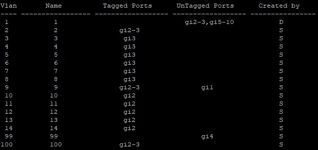](https://sioaubusson.fr/uploads/images/gallery/2026-03/bYEimage.png)
Maintenant que nos VLANS sont configurées nous pouvons à présent attaquer les routes qui reliera tous nos vlan au port de notre routeur gi5 192.168.80.2.
ip route 0.0.0.0 0.0.0.0 192.168.80.1 -> Route par défaut
ip route 192.168.10.0 255.255.255.0 192.168.80.1
ip route 192.168.20.0 255.255.255.0 192.168.80.1
ip route 192.168.30.0 255.255.255.0 192.168.80.2
ip route 192.168.40.0 255.255.255.0 192.168.80.2
ip route 192.168.50.0 255.255.255.0 192.168.80.2
ip route 192.168.60.0 255.255.255.0 192.168.80.2
ip route 192.168.70.0 255.255.255.0 192.168.80.2
ip route 192.168.90.0 255.255.255.0 192.168.80.2
ip route 192.168.100.0 255.255.255.0 192.168.80.2
ip route 192.168.110.0 255.255.255.0 192.168.80.2
ip route 192.168.120.0 255.255.255.0 192.168.80.2
ip route 192.168.130.0 255.255.255.0 192.168.80.2
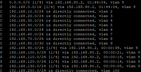
Dès que nous avons fini nos commandes ip route, pour les vérifier nous pouvons faire la commande suivante :
[](https://sioaubusson.fr/uploads/images/gallery/2026-03/Kgrimage.png)